


Wszystkie produkty
-
Kondensator ceramiczny wysokiego napięcia
-
Kondensatory klamek wysokiego napięcia
-
Kondensator foliowy wysokiego napięcia
-
Kondensatory linii pod napięciem
-
Urządzenie przeciwprzepięciowe
-
Wyłącznik próżniowy wysokiego napięcia
-
Czujnik temperatury rozdzielnicy
-
Transformatory napięciowe
-
Pojemnościowy detektor napięcia
-
Pojemnościowy dzielnik napięcia
-
Izolator pojemnościowy
-
Warystor MOV z tlenkiem metalu
-
Termistor PTC NTC
-
Rezystory wysokonapięciowe
-
 Richard„XIWUER jest bardzo innowacyjny. Zapewnili doskonałą, intuicyjną obsługę, patrząc w przyszłość, czego możemy potrzebować”.
 -
 Mikrofon„Zaangażowanie XIWUER w projektowanie różnych specyfikacji, aby spełnić nasze rygorystyczne wymagania dotyczące przetwarzania, jest świadectwem naszych lat badań i rozwoju”.
 -
 Ożenić"XIWUER ma imponujące możliwości badawcze i wykazuje dobre możliwości prototypowania oraz wysoką jakość produktu."
Osoba kontaktowa :
Wang Hong
Numer telefonu :
+8615891045672
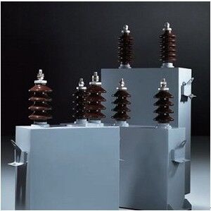
Wodoochłodzony kondensator grzewczy elektryczny o napięciu nominalnym 0,75-1,2 kV i częstotliwości 40-24.000 Hz dla zastosowań wysokiego napięcia

Szczegóły Produktu
| Podkreślić | Chłodzony wodą elektryczny kondensator grzewczy,Kondensator ceramiczny wysokiego napięcia o napięciu znamionowym 0,75–1 |
||
|---|---|---|---|
opis produktu
Kondensator grzałkowy elektryczny
Kluczowe specyfikacje techniczne
- Odchylenie pojemności: ±10%. Stosunek maksymalnej do minimalnej wartości pojemności dla każdej fazy i grupy nie powinien przekraczać 1,1.
- Wykładnik strat dielektrycznych tanδ (dla dielektryka pełnfoliowego) przy napięciu znamionowym Un i 20°C:
- Un ≤ 1kV: tanδ ≤ 0,0015
- Un > 1kV: tanδ ≤ 0,0012
- Wytrzymałość izolacji: Wytrzymuje napięcie probiercze 1kV o częstotliwości sieciowej przez 1 minutę między zaciskami a obudową.
- Temperatura wody chłodzącej na wlocie nie powinna przekraczać 30°C.
- Dla kondensatorów o Qn ≤ 1000 kvar, przepływ wody ≥ 4 l/min
- Dla kondensatorów o Qn ≥ 1000 kvar, przepływ wody ≥ 6 l/min
- Długotrwałe przeciążenie napięciowe (nieprzekraczające 4 godzin w ciągu 24 godzin) nie powinno przekraczać 1,1Un.
- Długotrwałe przeciążenie prądowe (w tym prądy harmoniczne) nie powinno przekraczać 1,35In.
- Instalacja wewnętrzna, na wysokości nieprzekraczającej 1000m.
- Temperatura otaczającego powietrza w miejscu instalacji i eksploatacji nie powinna przekraczać 50°C.
- Miejsce instalacji wolne od silnych drgań mechanicznych, szkodliwych gazów/oparów i pyłów wybuchowych.
- Wodnokanałowe, w pełni foliowe kondensatory grzałkowe elektryczne typu RWM i RFM są zgodne z JB71
Zastosowanie
Głównie stosowane w sterowanych lub regulowanych systemach zasilania prądem przemiennym o napięciu znamionowym nieprzekraczającym 3,6kV i częstotliwości od 40 do 24 000Hz. Specjalnie zaprojektowane do poprawy współczynnika mocy w urządzeniach do ogrzewania indukcyjnego, topienia i mieszania lub odlewania, a także w podobnych zastosowaniach.
Konstrukcja
Kondensator grzałkowy elektryczny składa się z następujących głównych elementów:
- Rdzeń: Rdzeń składa się z wielu równoległych elementów. Każdy element kondensatora jest nawinięty z papieru kondensatorowego (dielektryka) i przewodników aluminiowych (płyt). Wszystkie płyty elementów wystają poza dielektryk. Jedna płyta jest spawana z rurą wody chłodzącej, która łączy się ze studzienką uziemiającą lub płytą uziemiającą na pokrywie, służąc jako zacisk ogólny dla tej płyty.
- Druga płyta jest izolowana od obudowy. Łączy się z szyną zbiorczą za pomocą płyty łączącej i jest wyprowadzona przez porcelanowy izolator na pokrywie.
- Obudowa: Obudowa jest prostokątna z przyspawanymi po obu stronach uszami transportowymi do przenoszenia. Pokrywa posiada izolator porcelanowy z ponumerowanym prętem i studzienkę uziemiającą lub płytę uziemiającą.
Warunki środowiska pracy
- Kondensatory muszą być instalowane bez wibracji. Dopuszcza się instalację w pobliżu grzejników, pod warunkiem że materiały niepalne tworzą solidną ścianę działową otaczającą kondensatory lub kondensatory są umieszczone w oddzielnych metalowych szafach.
- Aby zapobiec uszkodzeniu rur wody chłodzącej kondensatora, temperatura otoczenia w miejscu instalacji nie może spaść poniżej ±2°C.
- Kondensatory muszą być instalowane pionowo (izolatory porcelanowe skierowane do góry). Surowo zabrania się przenoszenia kondensatorów za ich izolatory porcelanowe. Zachować minimalny odstęp 20 mm między kondensatorami.
- Połączenia między rurami wody chłodzącej kondensatora oraz między rurami wody chłodzącej a rurami źródła wody muszą być wykonane z elastycznych węży gumowych. Rury wody chłodzącej mogą być łączone szeregowo, ale nie więcej niż trzy kondensatory. Rury spustowe nie mogą być zasłonięte i powinny być umieszczone w łatwo dostępnych miejscach, aby stale monitorować odpływ wody.
- Temperatura wody chłodzącej na wlocie nie może przekraczać +30°C, a na wylocie nie może przekraczać +35°C.
- Podczas szeregowego łączenia wielu rur wody chłodzącej (nie więcej niż trzy jednostki), należy regulować ciśnienie i przepływ wody, aby kontrolować różnicę temperatur między wodą na wlocie i wylocie, zapewniając, że temperatura na wylocie nie przekracza +35°C. Ciśnienie na wlocie wody chłodzącej nie może przekraczać 4 atmosfer.
- W przypadku przerwania dopływu wody z powodu awarii, należy natychmiast odłączyć zasilanie kondensatora. Gdy kondensator jest wyłączony z eksploatacji z powodu awarii, należy całkowicie opróżnić całą wodę z rur wody chłodzącej.
- Przy równoległym stosowaniu wielu zacisków grupowych na kondensatorze, należy użyć elastycznych płyt łączących. Główny zacisk wyjściowy musi być podłączony z elastycznej płyty łączącej, a nie z żadnego indywidualnego zacisku grupowego. Przekrój płyty łączącej nie może być mniejszy niż 2,5 cm².
- Jeśli napięcie linii przekracza napięcie znamionowe kondensatora, należy dostosować liczbę kondensatorów połączonych szeregowo lub połączyć równolegle zaciski kondensatorów pracujących szeregowo.
Specyfikacje produktu
| Nr seryjny | Model | Napięcie znamionowe Un/kV | Moc znamionowa Qn/kvar | Częstotliwość Hz/kHz | Pojemność znamionowa Cn/μF |
|---|---|---|---|---|---|
| 1 | RFM0.75-360-0.5S | 0.75 | 360 | 0.5 | 4x50.9 |
| 2 | RFM0.75-750-0.5S | 0.75 | 750 | 0.5 | 6x70.7 |
| 3 | RFM1.0-750-0.5S | 1.0 | 750 | 0.5 | 6x39.8 |
| 4 | RFM1.1-750-0.5S | 1.1 | 750 | 0.5 | 6x32.9 |
| 5 | RFM1.2-750-0.5S | 1.2 | 750 | 0.5 | 6x27.6 |
| 6 | RFM0.375-180-1S | 0.375 | 180 | 1.0 | 4x50.9 |
| 7 | RFM0.375-360-1S | 0.375 | 360 | 1.0 | 6x67.9 |
| 8 | RFM0.5-180-1S | 0.5 | 180 | 1.0 | 4x28.6 |
| 9 | RFM0.5-360-1S | 0.5 | 360 | 1.0 | 4x57.3 |
| 10 | RFM0.75-360-1S | 0.75 | 360 | 1.0 | 4x25.5 |
| 11 | RFM0.75-640-1S | 0.75 | 640 | 1.0 | 4x45.3 |
| 12 | RFM0.75-750-1S | 0.75 | 750 | 1.0 | 4x53.1 |
| 13 | RFM0.75-1000-1S | 0.75 | 1000 | 1.0 | 6x47.2 |
| 14 | RFM1.0-360-1S | 1.0 | 360 | 1.0 | 4x14.3 |
| 15 | RFM1.0-750-1S | 1.0 | 750 | 1.0 | 4x29.8 |
| 16 | RFM1.0-1000-1S | 1.0 | 1000 | 1.0 | 4x39.8 |
| 17 | RFM1.2-360-1S | 1.2 | 360 | 1.0 | 4x9.95 |
| 18 | RFM1.2-750-1S | 1.2 | 750 | 1.0 | 4x20.7 |
| 19 | RFM1.2-1000-1S | 1.2 | 1000 | 1.0 | 4x27.6 |
| 20 | RFM0.75-750-2S | 0.75 | 750 | 2.0 | 4x26.5 |
| 21 | RFM0.75-1000-2S | 0.75 | 1000 | 2.0 | 6x23.6 |
| 22 | RFM1.0-750-2S | 1.0 | 750 | 2.0 | 4x14.9 |
| 23 | RFM1.0-1000-2S | 1.0 | 1000 | 2.0 | 6x13.3 |
| 24 | RFM1.2-750-2S | 1.2 | 750 | 2.0 | 4x10.4 |
| 25 | RFM1.2-1000-2S | 1.2 | 1000 | 2.0 | 6x9.21 |
| 26 | RFM0.375-360-2.5S | 0.375 | 360 | 2.5 | 4x40.7 |
| 27 | RFM0.375-750-2.5S | 0.375 | 750 | 2.5 | 6x56.6 |
| 28 | RFM0.5-360-2.5S | 0.5 | 360 | 2.5 | 4x22.9 |
| 29 | RFM0.5-750-2.5S | 0.5 | 750 | 2.5 | 6x31.8 |
| 30 | RFM0.5-1000-2.5S | 0.5 | 1000 | 2.5 | 6x42.4 |
| 31 | RFM0.75-360-2.5S | 0.75 | 360 | 2.5 | 4x10.2 |
| 32 | RFM0.75-750-2.5S | 0.75 | 750 | 2.5 | 4x21.2 |
| 33 | RFM0.75-1000-2.5S | 0.75 | 1000 | 2.5 | 6x18.9 |
| 34 | RFM0.375-360-4S | 0.375 | 360 | 4.0 | 4x25.5 |
| 35 | RFM0.375-640-4S | 0.375 | 640 | 4.0 | 6x30.2 |
| 36 | RFM0.375-750-4S | 0.375 | 750 | 4.0 | 6x35.4 |
| 37 | RFM0.5-360-4S | 0.5 | 360 | 4.0 | 4x14.3 |
| 38 | RFM0.5-750-4S | 0.5 | 750 | 4.0 | 6x19.9 |
| 39 | RFM0.5-1000-4S | 0.5 | 1000 | 4.0 | 6x26.5 |
| 40 | RFM0.75-360-4S |
Polecane produkty